From Visual Image to Measurable Geometry
In dialogue with Thomas Vain, Digital Lab Manager at DTU Skylab, I examined the difference between capturing the visual appearance of a physical component and creating a dimensionally accurate digital representation.
A photograph records colour, surface and visible shape, but does not automatically contain reliable information about the component’s physical dimensions. Computer vision can be used to segment the image and isolate each component from its background. When the image is calibrated against a known scale or reference, its pixel-based geometry can be translated into physical measurements such as width and surface area.
This distinction was important to my process. A recognisable digital outline is not sufficient if the component is intended for further pattern development. Both the geometry and its scale must remain accurate as the material moves from an analogue object into a digital design environment.

Research framework presented by Thomas Vain: photography captures the visual material, segmentation isolates its geometry, and calibration connects the digital image to real-world measurements.
From Physical Component to Digital Pattern
The initial research was conducted at DTU Skylab in collaboration with Thomas Vain, Digital Lab Manager. The purpose was to investigate whether deconstructed post-consumer garment components with irregular edges could be registered accurately and transferred into a digital pattern-development workflow.
A back pocket and a larger front panel from a pair of jeans were placed directly on a digitising tablet. Using the Logic Trace System for Apparel, I traced each component at full scale and exported the registered geometry as a DXF file for further examination in CLO3D.
The physical components were subsequently measured and compared with their digital representations. The test confirmed that Logic Trace could register the irregular outlines and transfer the components into CLO3D at their actual dimensions.
However, the DXF file transferred only the geometry of each component. When opened in CLO3D, the pieces appeared as uniform blue pattern shapes without the original textile surface, seams, wear marks or other visual information contained in the physical denim.
To recreate the full component digitally, the geometric transfer therefore had to be supplemented by a separate image of the physical textile piece, which could then be applied to the corresponding pattern piece in CLO3D.
The Skylab test established that deconstructed textile components could be captured and transferred at full scale. It also revealed that the workflow consisted of two separate processes: transferring the geometry and reconnecting it with the material’s visual information. This became the starting point for the subsequent test of the workflow through a complete garment.
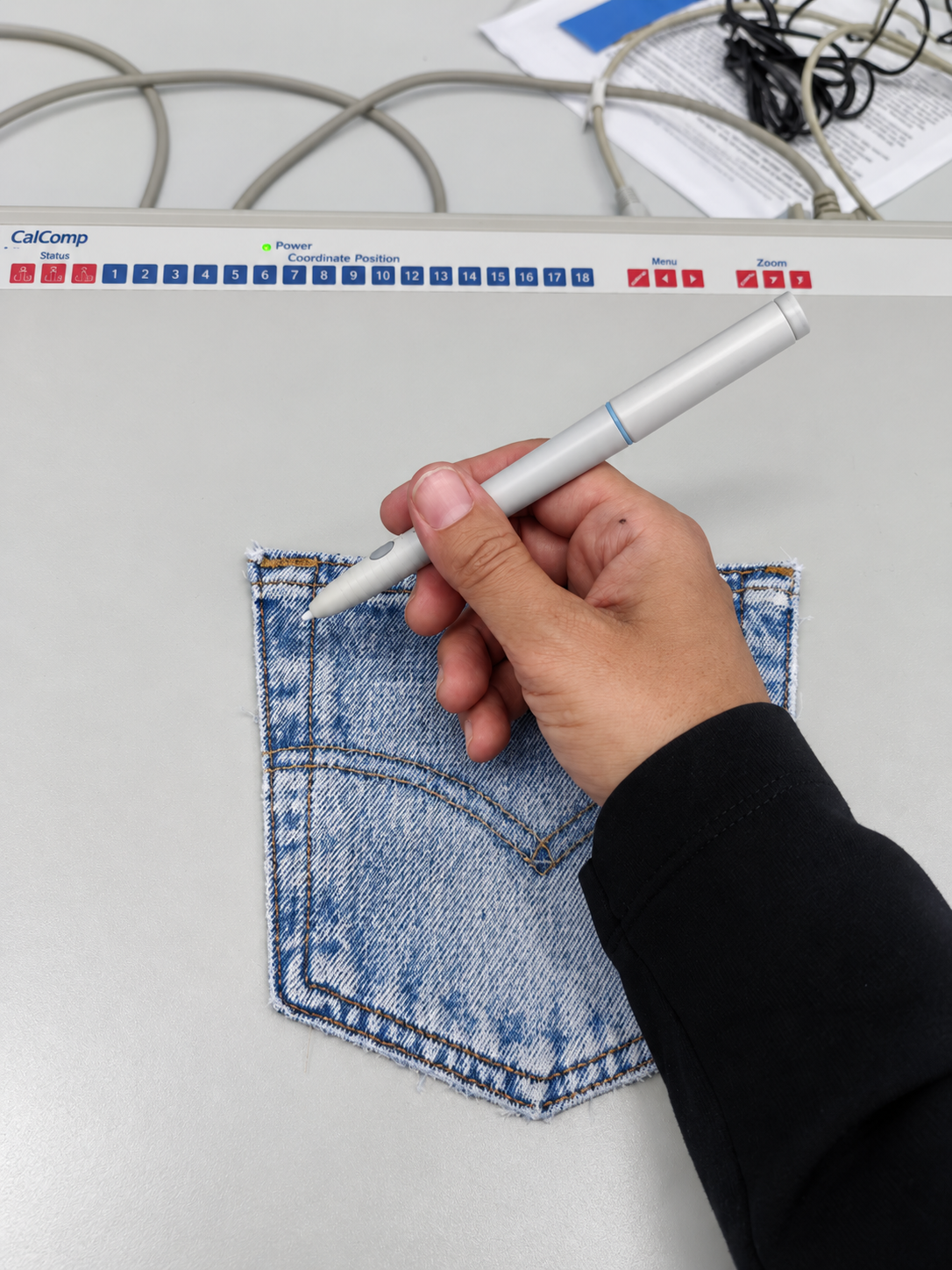
Tracing the outline of a deconstructed denim pocket on the digitising tablet.

Positioning a deconstructed denim front panel for digital registration.
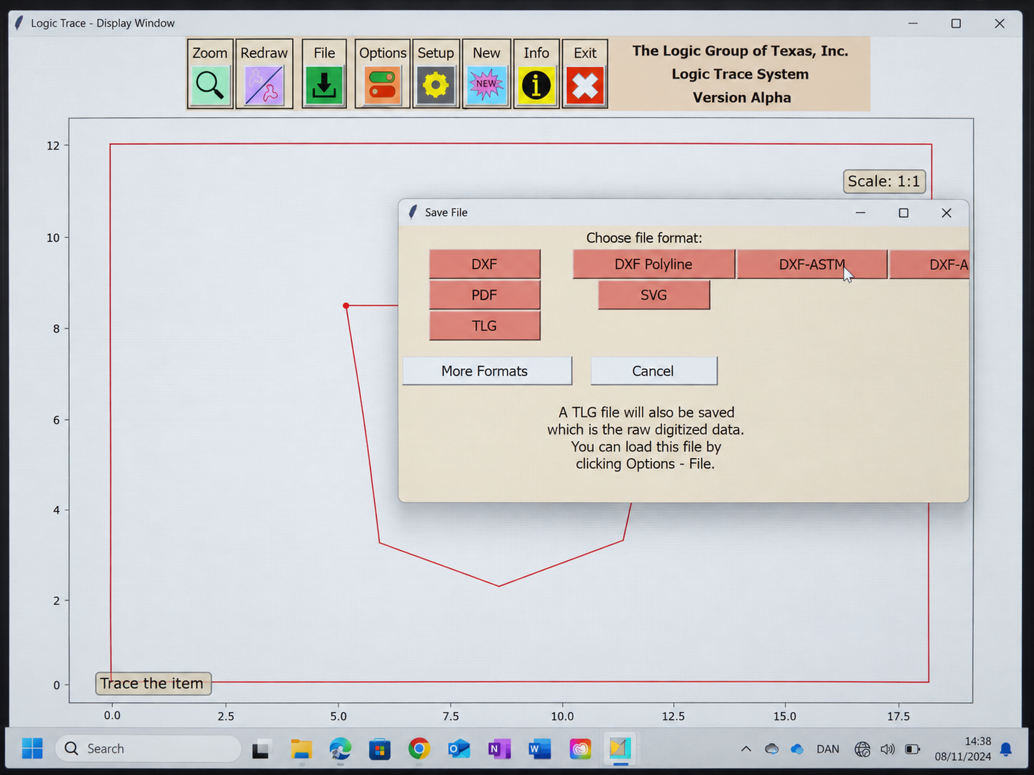
Preparing the registered pocket outline for export from Logic Trace.

Preparing the registered front-panel geometry for export from Logic Trace.

Examining the imported pocket as a 2D pattern piece in CLO3D.

The traced pocket outline displayed as digital geometry in Logic Trace.

Measuring the physical denim pocket to establish a reference for accuracy.

Examining the imported pocket and front panel together in CLO3D.

Measuring the upper edge of the physical denim front panel.

Checking the segmented measurements of the imported front-panel geometry.

The deconstructed pocket and front panel positioned on the digitising tablet.
Using the digital pen, I trace the existing edges and curves of the deconstructed denim panel directly on the digitising tablet. The physical outline is registered at full scale in Logic Trace before being exported for evaluation in CLO3D.
Testing the Workflow Through a Complete Garment
Following the initial research at DTU Skylab, I developed a second test to examine how the process could function as part of an applied design workflow.
The first test established that Logic Trace could register the irregular outlines of deconstructed textile components at full scale and transfer their geometry as DXF files. When opened in CLO3D, however, the imported pieces appeared as flat blue pattern shapes. The DXF file retained the outline and dimensions, but not the material surface, original seams or other visual information carried by the physical component.
To investigate the complete workflow, I worked from an existing pattern for a hybrid garment combining elements of shorts and a skirt. As the complete pattern pieces exceeded the dimensions of the digitising tablet, they were divided into smaller sections. Each section was traced separately in Logic Trace and exported as a DXF file. In CLO3D, the corresponding sections were aligned and merged to reconstruct the complete pattern pieces.
A separate photograph of each physical component was then applied to its corresponding digital pattern piece. This created a two-part process: first transferring the component’s geometry, and then reconnecting that geometry with the visual information carried by the original textile.
Once the components had been reconstructed and assembled in CLO3D, I could examine whether their dimensions and proportions had been retained, how the pieces related to one another, and how the complete garment translated into a digital representation.
The test demonstrated how deconstructed garment components could become active material within a digital design process. It also identified a point requiring further development: the connection between geometric registration and the transfer of material information into CLO3D. A more integrated solution could make it easier to digitise, combine and redesign existing textile components without treating geometry and material identity as two separate processes.
The screen recording documents how the separate pattern sections were traced and prepared for export in Logic Trace before being reconstructed in CLO3D.
The following images show the reconstructed pattern components in CLO3D. The red lines indicate where separately digitised sections were aligned and merged to recreate the complete pattern pieces.

The red line indicates where the separately digitised sections of the curved component were merged in CLO3D.
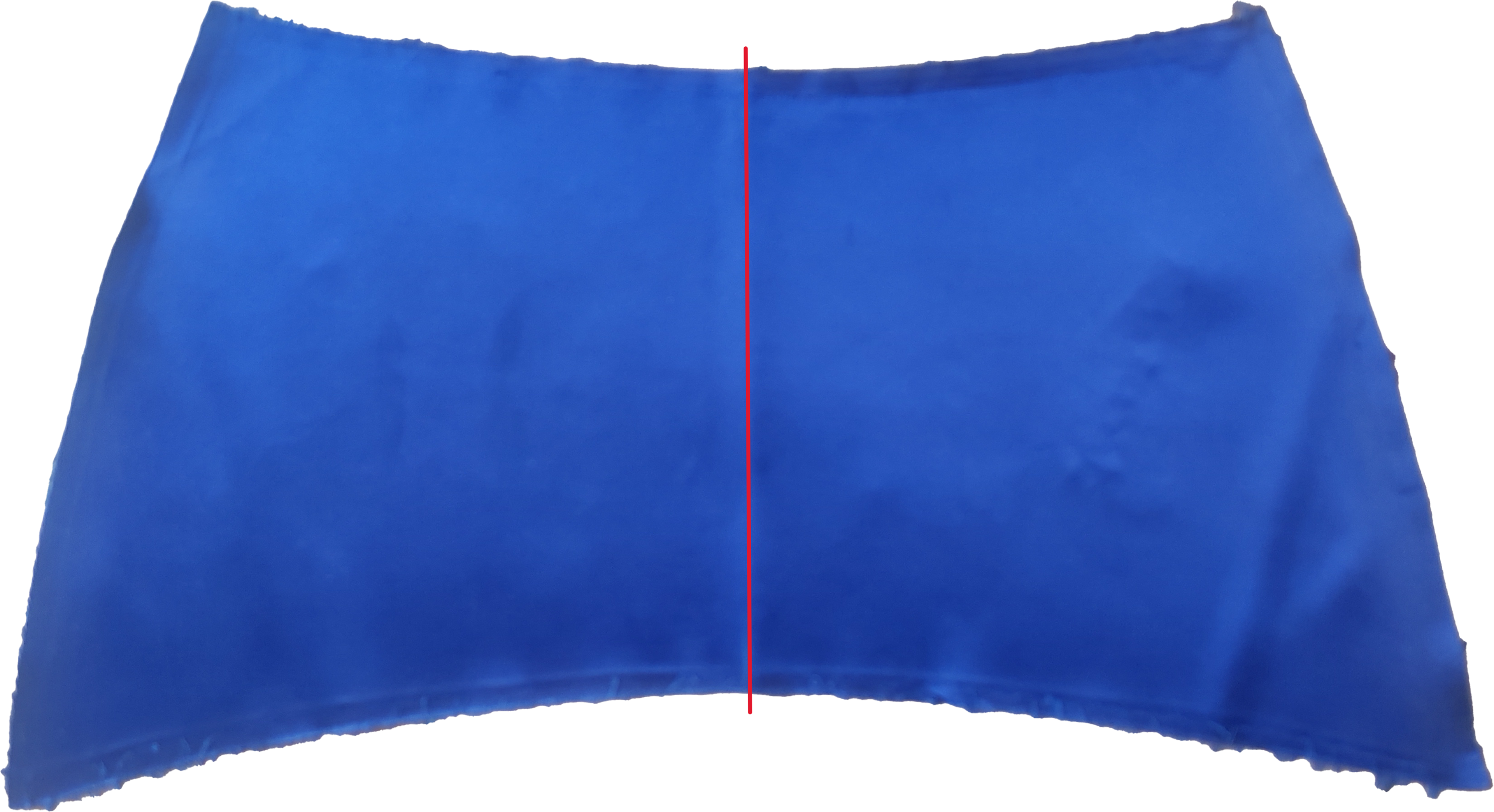
The red line indicates where the two sections of the curved front flap were merged in CLO3D.
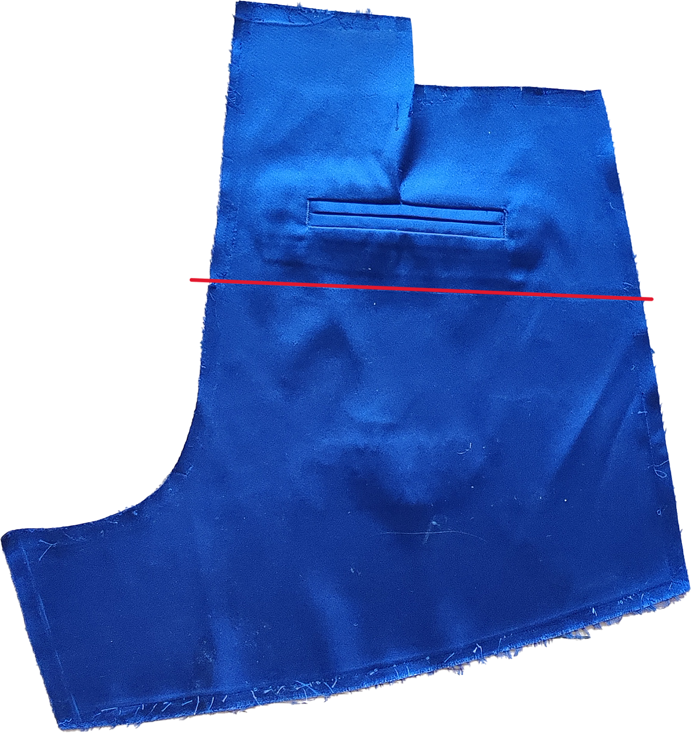
The red line marks where the separately digitised back sections were merged in CLO3D.

The red line marks where the separately digitised front sections were merged in CLO3D.
From Reconstructed Pattern to Digital Prototype
Once the pattern sections had been aligned and merged, the reconstructed components were positioned around the avatar and virtually assembled in CLO3D. The front and back were developed separately before the curved front flap was added, and the complete garment was evaluated from multiple angles.
Photographic references of the original material were mapped onto the digital pattern pieces, creating a visual connection between the physical textile and its digital representation. The completed simulation made it possible to examine how the reconstructed geometry translated into proportion, volume and silhouette when assembled on the body.
This stage was not intended as a finished design validation, but as a test of the complete workflow. It demonstrated how physical pattern components could be digitised, reconstructed and used as the basis for further design development in CLO3D.

The reconstructed front components are positioned on the avatar to examine their scale and relationship to the body.

The reconstructed back components are positioned and prepared for virtual assembly in CLO3D.

The curved front flap is added, introducing the overlapping construction that defines the hybrid design.
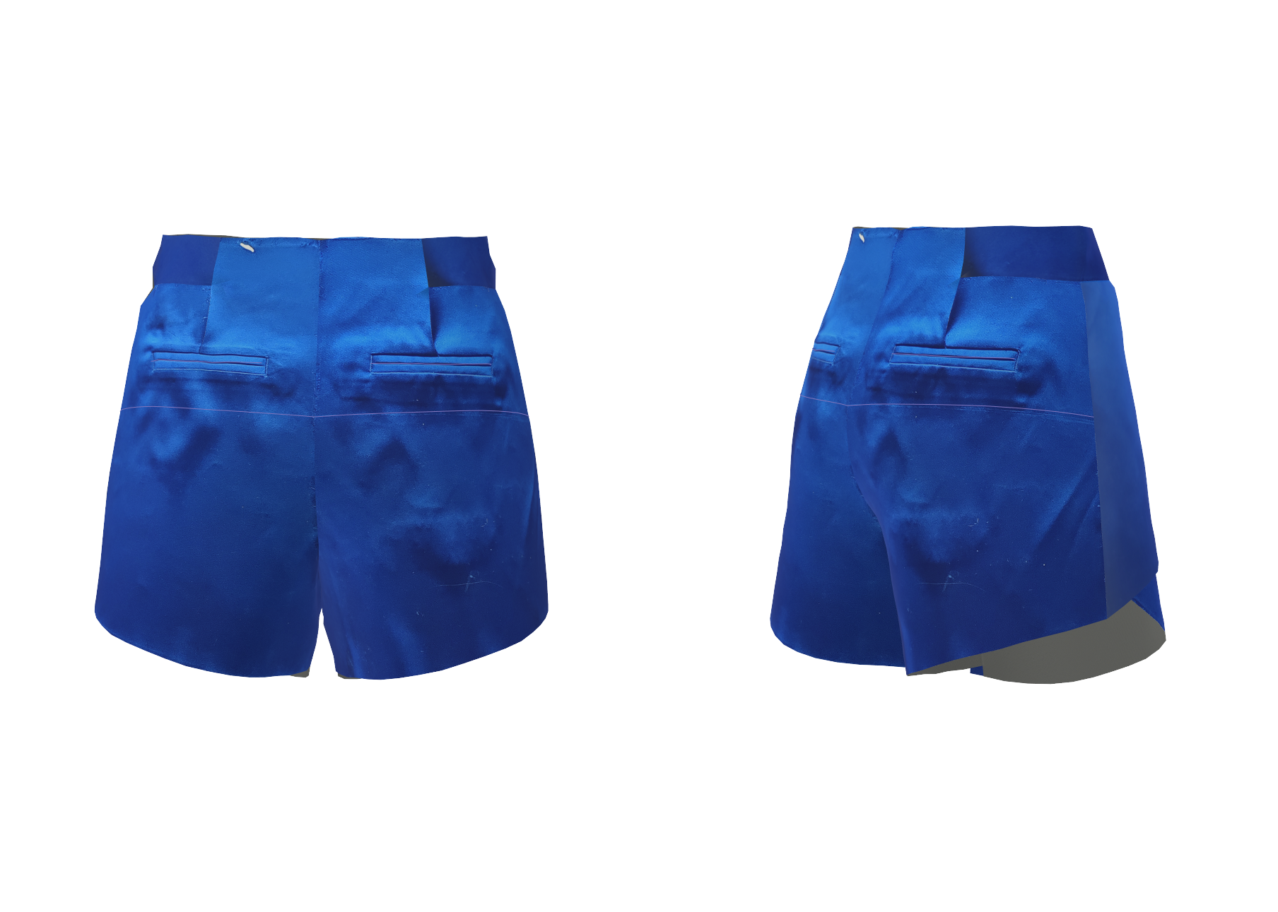
Front and back views of the assembled digital garment, with photographic material references mapped onto the reconstructed pattern pieces.

The completed digital prototype is viewed as part of a full silhouette to assess its proportion, volume and overall design expression.
From Workflow Research to Physical Prototypes
The digital tests established how irregular textile components could be registered, reconstructed and introduced into a digital design workflow. They also revealed where the process remained fragmented, particularly between the transfer of accurate geometry and the material information carried by the original textile.
The next phase moved from technological testing to physical prototype development. Through an analogue re-make process, the available dimensions, fibre direction, previous seams, colour variations and traces of wear became active conditions within the construction of a denim jacket and a wool vest.
From Material Mapping to Construction
The physical prototypes were developed through an analogue remake process in which each source garment was first deconstructed into usable textile sections.
The available surface area, fibre direction, previous seams, pockets, wear marks and colour variations were mapped before the pattern pieces were positioned. Where a complete pattern piece could not fit within a single textile section, several components were cut and joined to reconstruct the required shape.
The visual construction guides document the relationship between the original garments, pattern placement, cut components and final assembly. They were developed to make the design decisions legible and to support a more consistent workflow when working with variable post-consumer materials.


Prototype Testing in Everyday Use
To examine how the prototypes functioned beyond the studio, material innovation specialist Julie Verdich tested the denim jacket and wool vest in different everyday contexts. Using an adapted Daily Catalogue method, she documented how the garments were worn, combined and experienced over several days.
The testing showed that the oversized constructions supported flexible styling and layering across different situations. The denim jacket was experienced as comfortable and adaptable, while the wool vest worked particularly well as a layered piece.
The observations also identified areas for further development. The vest’s fastening could be simplified to improve the wearing experience, while a residual smell in the post-consumer denim highlighted the need for a more consistent pre-treatment process before construction.
Rather than treating the prototypes as finished outcomes, the testing made it possible to evaluate how material choices, construction details and previous traces of use affected comfort, functionality and the experience of the garments in practice.


What the Pilot Established
The pilot established that post-consumer textile components can be approached as both measurable geometry and material-specific design resources. The digital tests demonstrated that irregular components could be registered at full scale and reconstructed in CLO3D. At the same time, they revealed a fragmented point in the workflow: geometric data and visual material information still had to be transferred through separate processes.
The physical prototypes demonstrated a different but connected principle. When working with existing garments, available dimensions, fibre direction, previous seams, fading and traces of wear cannot be separated from the construction process. These material conditions influenced the placement of pattern pieces, the joining of components and the final expression of both the denim jacket and the wool vest.
The visual construction guides made these material and construction decisions more legible and provided a foundation for documenting and repeating the re-make process. Subsequent testing in everyday use identified specific areas for further development, including fastening details, textile pre-treatment and the connection between digital registration and physical construction.
The outcome of the pilot was therefore not a standardised production system, but a documented workflow, two physical prototypes and a clearer understanding of where analogue knowledge and digital technology can support one another and where further development is still required.


